
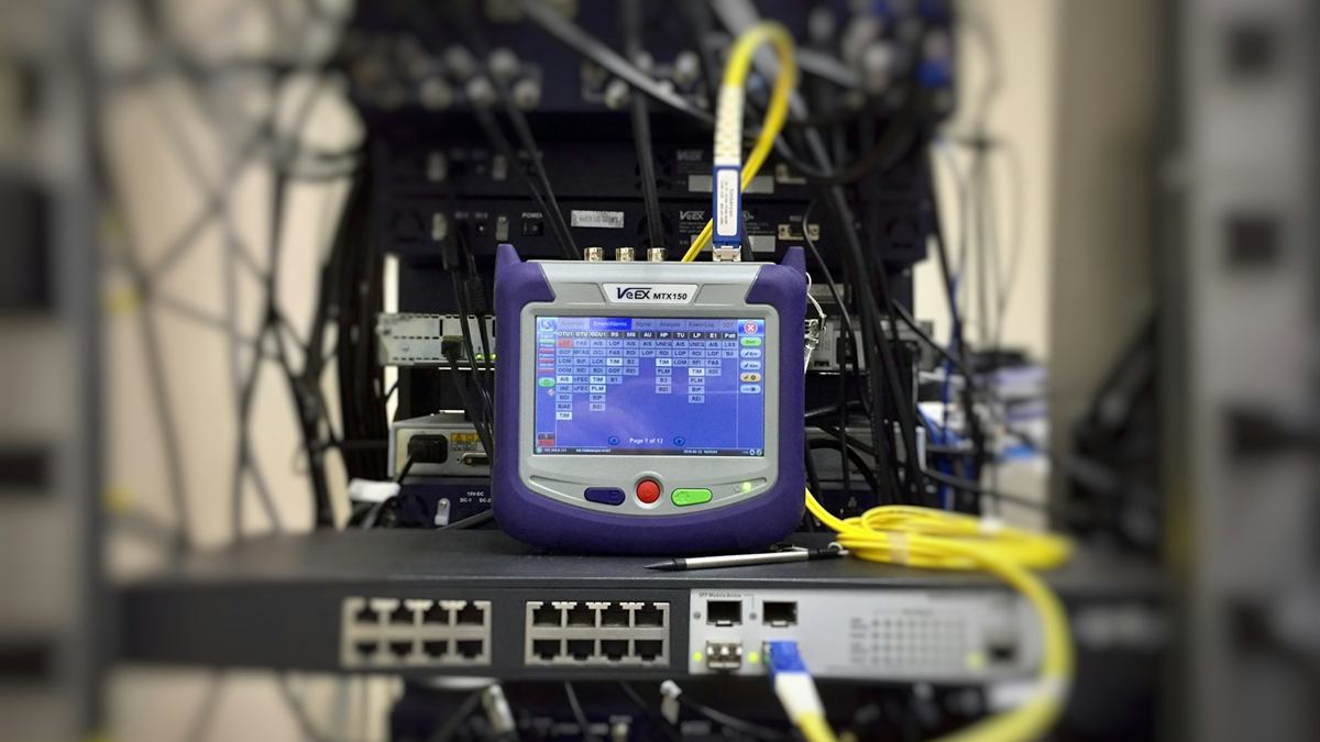
DOM vs Optical Power Meter vs OTDR: Choose the Right Evidence
Use digital optical monitoring (DOM) for in-service transceiver telemetry, an optical power meter or optical loss test set for calibrated power or end-to-end loss, and an optical time-domain reflectometer (OTDR) to locate reflective and loss events along a fiber. These tools answer different questions. A DOM reading is not a cable certification, and an OTDR trace is not a substitute for a properly referenced insertion-loss test.
Route the question to the tool
- DOM or DDM: trend module temperature, voltage, bias, transmit power and receive power from the host.
- Optical power meter: measure the power arriving at a point from a known source or active transmitter.
- Optical loss test set: measure end-to-end insertion loss with a defined source, reference method and receiver.
- OTDR: estimate event location, reflectance and loss along the fiber from one end.
Understand the measurement boundary
DOM belongs to the transceiver and host path, so accuracy and calibration depend on the exact module and platform. It is valuable for trends and directional comparison but does not certify the passive channel.
A power meter reports power at its detector. Loss requires a known reference or a comparison with a known transmitter.
When digital monitoring is not implemented
A message that digital monitoring is not implemented does not prove that the optical path or module has failed. First verify that the exact module supports DOM or digital diagnostic monitoring (DDM), that the host platform and software expose it, and that the correct command or management interface is being used.
When telemetry is unavailable, preserve module identity, interface alarms and error counters, then measure the required point with an external optical power meter or loss-test set. Use an OTDR only when the question is event location or route condition. Do not invent a receive-power value from link state alone.
Use insertion-loss testing for acceptance
Define the reference method, test cords, included connectors, wavelengths and direction. An OLTS can compare the measured channel loss with the project limit and record margin.
Changing the reference or test-cord condition invalidates direct comparison with earlier results.
Use an OTDR to locate, not merely total, loss
An OTDR trace can identify connectors, splices, bends, breaks and reflective events by distance. Launch and receive fibers are often needed to evaluate the first and last connections, and pulse-width choices affect resolution and dead zones.
Bidirectional traces may be required to interpret asymmetric events. Use the same fiber type and correct settings for the route.
Combine evidence without mixing units
For a low-receive-power alarm, begin with both-end DOM to identify direction, verify power independently when needed, then use insertion-loss testing or OTDR if the passive path is disputed. For high errors with normal power, add lane, FEC, connector and configuration evidence.
Record dBm for absolute power and dB for loss. Do not subtract or compare values without confirming their meaning and reference.
Decision table
- Need continuous trend: use DOM where supported
- Need received power at one point: use a calibrated optical power meter
- Need end-to-end channel loss: use a referenced OLTS or light source and power meter
- Need event location: use an OTDR with suitable launch and receive fibers
- Need service acceptance: combine the specified physical test with traffic and error evidence
Related Axonode guidance
Technical sources
- Fluke Networks network-engineer troubleshooting tools
- Fluke Networks fiber troubleshooting white paper
Frequently asked questions
Can DOM replace an optical power meter?
Not when calibrated independent evidence is required. DOM is useful operational telemetry with module- and platform-dependent accuracy.
Can an OTDR measure total insertion loss?
It can estimate loss, but end-to-end acceptance is normally based on the specified referenced loss-test method.
Why are dBm and dB different?
dBm is an absolute power level; dB is a relative gain or loss.
Which tool finds a bad connector location?
An OTDR can locate reflective or loss events, while inspection and segment testing confirm the physical connector condition.
What should I do when diagnostic monitoring is not implemented?
Confirm module, host and software support first. If DOM or DDM is genuinely unavailable, use external measurement and interface error evidence for the exact decision instead of treating missing telemetry as a failed optic.
Send the question and measurement boundary first
Provide the host and optic identities, route diagram, symptom, required acceptance standard, existing DOM data, power or loss readings, OTDR traces and test setup. Axonode can help organize the optical requirement and replacement decision around the evidence each tool can actually provide.
Contact Axonode or review the optical transceiver portfolio.
 DOM vs Optical Power Meter vs OTDR: Choose the Right Evidence
 FEC Corrected vs Uncorrected Errors: Read the Trend Before Failure
 MPO Polarity Troubleshooting for Parallel Optics
 Tunable DWDM Transceiver Commissioning Checklist